
This article contains general recommendations for troubleshooting electrical issues. Electrical work should always be done by a qualified person in accordance with current safety rules and practices. Recommendations in this article are for illustrative purposes, and may not apply to your specific situation.
Commercial buildings can leverage 0-10V lighting to keep their spaces lit without low voltage. But what do you do when it doesn’t work correctly? In this blog, we look at how to troubleshoot 0-10V lighting.
What Is 0-10V?
0-10V lighting includes any lighting fixture that uses a low-voltage, direct current signal ranging from 0 to 10 volts to control light output. Typically, the 0-10V signal is used to adjust lighting intensity (brightness), but it can also be used to control the color of a fixture’s light output.
0-10V controls are found in both fluorescent and LED fixtures and generally utilize 4 wires: two line-voltage wires to provide power to the fixture and two low-voltage wires to provide the dimming signal.
0-10V applications are everywhere, so understanding how 0-10V lighting works is extremely important to anyone who operates in the commercial lighting space.
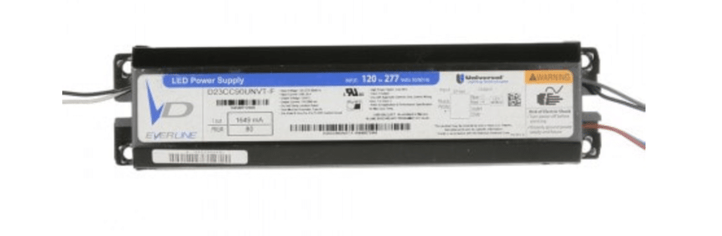
A typical 0-10V fluorescent ballast.
Symptom 1: Lights Won’t Turn On
Let’s cover some basic symptoms of your 0-10V lighting and go through the recommended steps to troubleshoot those symptoms, starting with “my lights won’t even come on!”.
The obvious place to start here is with your power wiring. 0-10V fixtures require power from a line-voltage source (in the U.S., likely 120 volts AC or 277 volts AC). However, most 0-10V fixtures require the use of a relay to turn this power on and off. Starting at the 0-10V dimming controller (examples of your controller might include a GRX-TVI, a dimming panel, or a 0-10V wall dimmer), check for input voltage compared against both ground and neutral (If this doesn’t make sense, give us a call, or reach out to a local electrician). If no power is coming into your controller, you’ll need to ensure that the appropriate breaker is turned on or that the incoming wiring is correct. (If voltage is present compared to the ground but not to neutral, you’ll need to have an electrician check your incoming power wiring).
If voltage is coming into the controller but is not leaving the relay, you’ll need to understand how your control system works.
If your controller operates as a stand-alone, you should be able to manipulate the relay using onboard buttons or keypads. Some 0-10V controllers are load-type interfaces, like the GRX-TVI. In that case, you would need to ensure the dimmer driving the interface is appropriate to drive the relay (Check out the dedicated GRX-TVI section below).
Lastly, if your 0-10V controller is a panel, you’ll need to check the programming. You can always temporarily bypass the relay by wiring your input wire directly to your output wire to see if this brings the light on. If you can’t get the relay to close and allow power through, you may need to reach out to the manufacturer of your controller for more assistance.
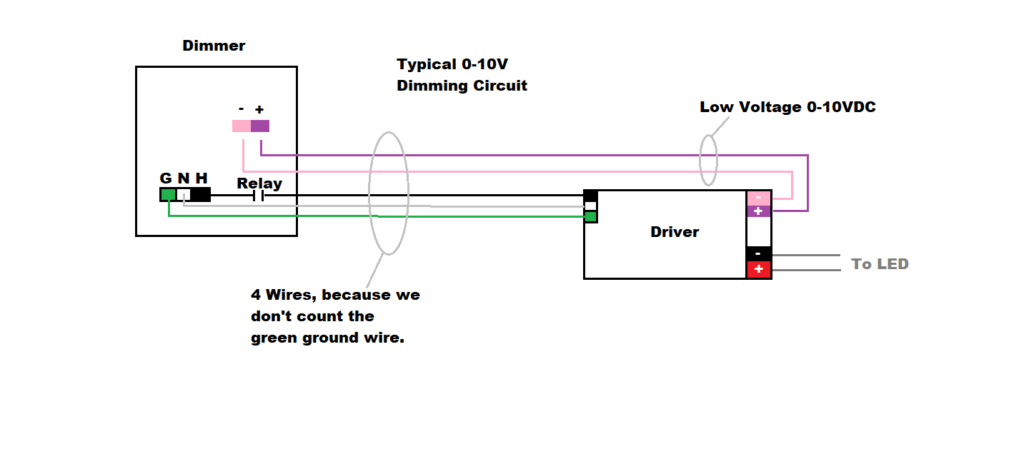
How a dimmer connects with a driver.
But what if you have power leaving the controller, but the light still won’t turn on? It’s time to move to the fixtures themselves.
The controller is likely wired to more than one fixture. If this is the case, I always recommend starting at the first fixture after the controller (if you know which one that is). Start by checking the incoming voltage and make sure it matches what left the controller, both to the ground and neutral. Also, check to make sure your incoming voltage matches the driver input. Most modern drivers are designed to be universal voltage and can accept either 120V or 277V, but not all! Next, I always recommend unwiring the low-voltage pair from the ballast or driver.
Remember, most commercial 0-10V applications follow IEC 60929, which means the ballast or driver should be sourcing the 0-10V signal. In these applications, disconnecting the low-voltage wires should be the equivalent of sending 10V or a full-bright signal to the fixture. If you verify that a 0-10V fixture has the proper incoming voltage, along with an open low-voltage pair of wires, that fixture should be on at 100%. If your fixture has proper line voltage, and the dimming wires are open and loose, the next step is to troubleshoot the fixture itself (Be careful, as this may void your fixture warranty. Try contacting the fixture manufacturer at this point).
If Your Fixture Is Fluorescent
Make sure the socket wires leaving the ballast are wired as required. Many dimming fluorescents require their sockets to be wired in parallel or “rapid-start” configuration. Make sure the lamps are new and sound, with no blackened ends. Make sure the number and wattage of the lamps match the ballast requirements. Look for a flash every few seconds, indicating that the ballast is trying to strike, as opposed to no flash, indicating no activity. Cycle power to the ballast, as some ballasts will “limit re-strikes” and essentially give up trying to light after a certain number of failures. Finally, try swapping the ballast.
If Your Fixture Is LED
There should be two output wires leaving the driver, usually red and black. These should carry a DC voltage to power the LED engine. These wires are polarity sensitive, so ensure they land correctly (typically red on positive and black on negative). If parts are easy to swap, you could try connecting a known good LED engine onto these output wires. Lastly, remember that an LED driver and LED engine must be matched appropriately. While rare, I have seen cases where the driver was not matched correctly to the LED engine, and the fixture would never turn on. Contact your fixture manufacturer in this case.
Symptom 2: Light Turns On and Off, With No Dimming
This one is a very common issue in the world of 0-10V dimming. I like to think of troubleshooting a 0-10V fixture, almost like troubleshooting two entirely different problems, because most 0-10V controllers use a relay to turn the fixture on and off and low-voltage dimming wires to dim the light up and down. In this case, we can ignore the relay portion and focus on the dimming portion.
Like before, I recommend starting at the controller. Find the low-voltage pair for the light you want to dim and check the voltage. Remember to set your meter to DC, and remember polarity! In older 0-10V applications, your positive wire will be purple, and your negative wire will be grey. According to the new standard, the gray wire is transitioning to pink.
Look at your dimming wire voltage and compare it to the desired output. If the dimmer calls for 100%, you should read something near 10 VDC. If the dimmer calls for 50%, you should read something near 5 VDC. If the dimmer is calling for 10%, you should read something near 1 VDC (Don’t get too worried about exactly what voltage you see. Getting close is the important part).
If the Voltage Seems Good, But the Light Doesn’t Dim
Move to the first fixture and check the same wires there. Does the voltage move up and down, but the light still doesn’t dim? Check your wiring to the fixture, and ensure the low-voltage wires are tightly connected to the ballast or driver. You can also try the “wire shorting method” here, as described below.
Another common issue is that the low-voltage wires might be connected to the wrong lighting zone. Remember that 0-10V lighting has one control (a relay) for on and off and another control (0-10V dimmer) for intensity, and it is fairly common to see these controls coming back on separate home runs to the controller. When this happens, the dimming signal can accidentally land on the wrong output, even if the relay home run is on the correct output.
One last thing to check… make sure your driver is compatible with your controller. You may need to contact the manufacturer for help, but ensuring sink/source compatibility is essential (read my 0-10V lighting explainer for more information on this).
Lastly, ensure you don’t have DALI/Lutron EcoSystem ballast or driver. These look almost identical to 0-10V ballasts and drivers, but they WILL NOT work in a 0-10V application.
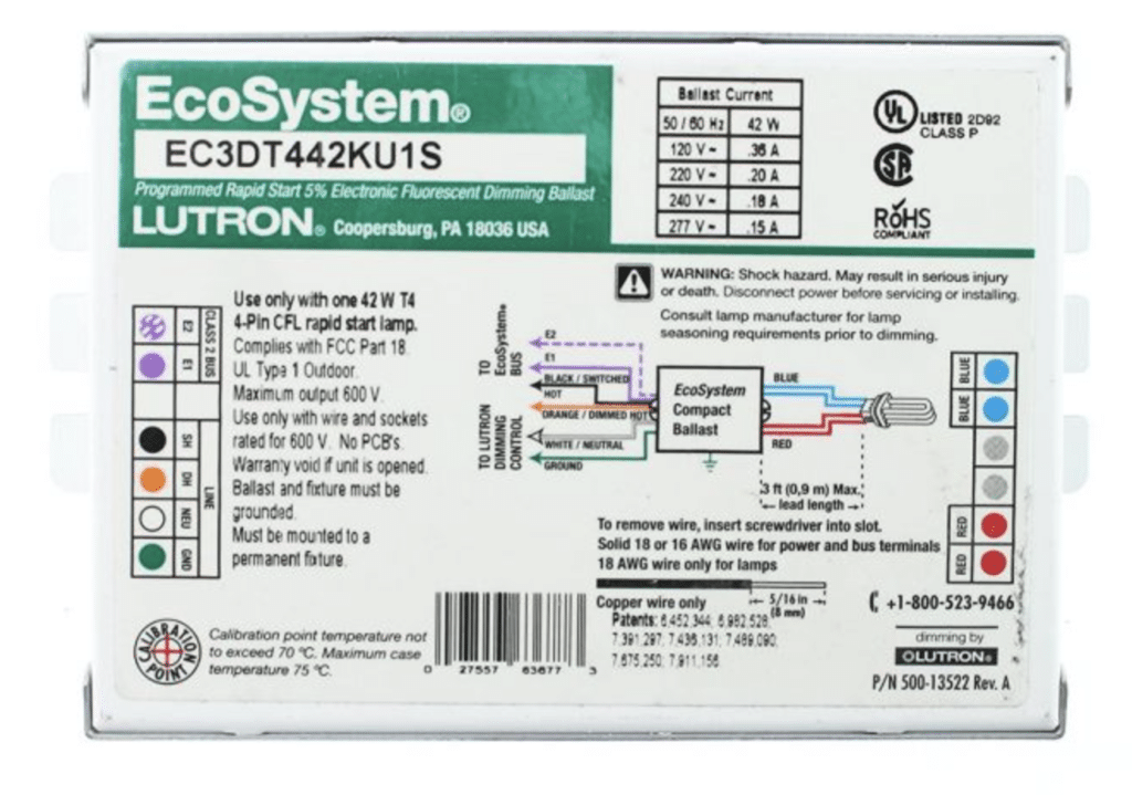
A Lutron EcoSystem ballast. Note the low-voltage terminals are labeled E1/E2, not positive and negative.
If the Voltage Is Not Reading Properly at the Controller
So, you expect to see 10 VDC at the controller, but that’s not what you’re getting? Start by disconnecting the 0-10V wires from the controller and reading them again. If your fixtures are sourcing the voltage (the most common case in commercial applications), they should send 10 VDC back to the controller on these low-voltage wires.
If there is not 10 VDC coming back on your low-voltage pair, something is wrong in the field. The voltage you see should inform your troubleshooting steps from here, but here are some common field issues:
- Some fixtures are wired backward. It is extremely common to see 0-10V wiring backward in one or more fixtures, and one fixture can mess up the dimming of a whole zone of lighting.
- Low-voltage gray wires have been connected to neutral wires. Take extreme caution with this one. If the low-voltage wires have been connected to 277V neutral wires, there could be a danger to personnel working on the wires, along with the danger of damaging equipment. Ensure a qualified electrician is working on this.
- Ballasts or drivers are not compatible. Make sure the ballasts or drivers are compatible with your dimmer. Consult specification sheets and contact manufacturers if required.
- Too many fixtures or too long of distances. Most controllers have a limit of fixtures and a wire length limit. Find this information on the appropriate spec sheet.
Depending on what you find, there are two troubleshooting methods you can use to focus on your problem area and find your problem, even in a room with hundreds of light fixtures.
The Wire Shorting Method
This is one of the handiest tests in all of 0-10V troubleshooting! First and foremost, do not try this method if you are not qualified to work with electrical equipment. Second, even if you are qualified, always check your wires for high voltages before shorting anything together. Remember, if you are troubleshooting wiring, someone did something wrong somewhere. The low-voltage gray wire was changed to pink because accidentally connecting the low-voltage gray to a 277V neutral was so common.
If the two low-voltage wires in a 0-10V application are shorted together, you simulate a low-end dimming condition, and all correctly wired fixtures should dim to a minimum. This test is not a cure-all, however. Some fixtures that are wired backward might still respond to the wire-shorting method. However, this test is excellent for finding individual fixtures that are not tightly connected or not tied into the correct dimming zone.
The Mid-Way Split
This method has uses outside of 0-10V troubleshooting and can be extremely useful in many troubleshooting arenas.
By splitting a zone of light, the troubleshooter can effectively cut their area of focus in half instantly, significantly reducing the number of fixtures they have to examine. If, for instance, you suspect that a driver has its low-voltage signal wires backwards, but you don’t know which driver to check, splitting the low-voltage wires at the halfway point will tell you in which group of lights the problem resides. If the problem goes away when the zone is split in half, you know that the problem exists in the further half. You can re-connect your split and find a new split point three-quarters of the way along. If the problem still exists, leave your split in place (I’ll explain this) and do a new split at the one-quarter mark.
There are some pitfalls of this method to be aware of. First, as I just said, it is essential to leave your splits “open” when the problem persists. Let’s say, for instance, that your lighting zone has 2 issues in fixtures 2 and 7.
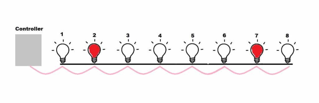
This chain of fixtures has two problems, one at fixture 2 and one at fixture 7.
If you start your split between 4 and 5, you’ll notice that your problem persists, indicating that a problem exists between fixtures 1 and 4.
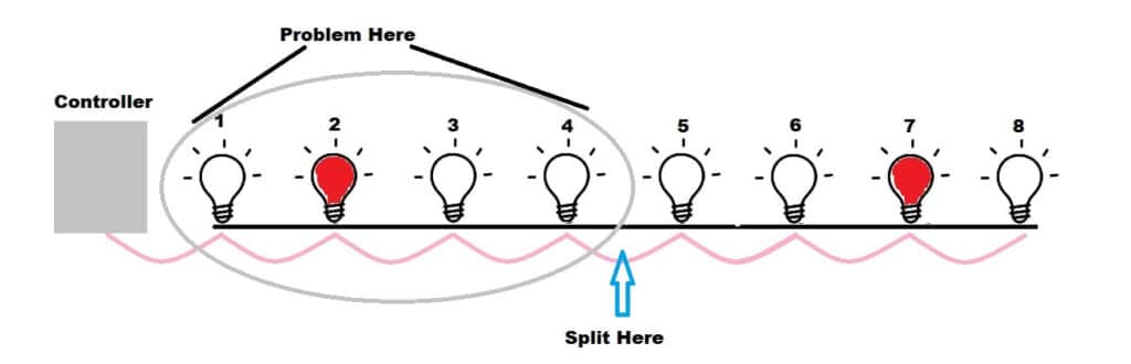
Splitting wiring between 4 and 5 would prove a problem exists between 1 and 4, but you still don’t know about 5 through 8.
In this example, you would be right! There is a problem between 1 and 4. But if you reconnect the split between 4 and 5, you could potentially re-introduce any problem after the split (in this case, the problem with fixture 7. It is important to make sure every problem on the close side of your split is corrected before you begin to re-introduce new sections into the system (My way of thinking about this is to make it work small before trying to make it work big).
Something else to consider… This method talks about splitting halfway because, mathematically, splitting mid-way through is the most efficient. However, the mid-way split doesn’t always make sense. For instance, sometimes splitting a lighting zone down to the first, and only the first fixture can function as a nice sanity check to make sure the controller is capable of even controlling one light. Once you have one functional fixture, you can add sections to see which section causes the system to fail.
Another thing to consider is that 0-10V doesn’t typically follow an actual daisy chain, as shown above. More frequently, 0-10V wiring follows “legs.” If this is the case for you, I recommend splitting the legs off individually to find out which legs are good and which are bad.
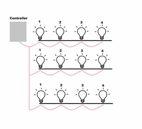
A more typical wiring layout for 0-10V lighting in a commercial space.
Troubleshoot the GRX-TVIOne of the most common 0-10V controllers in the world Lutron controls is the GRX-TVI. These units are highly versatile and can be used to incorporate 0-10V controls into a wide variety of systems and control types. However, the installation can be a little complex, and I wanted to take the opportunity to go over a few of the most common wiring issues.
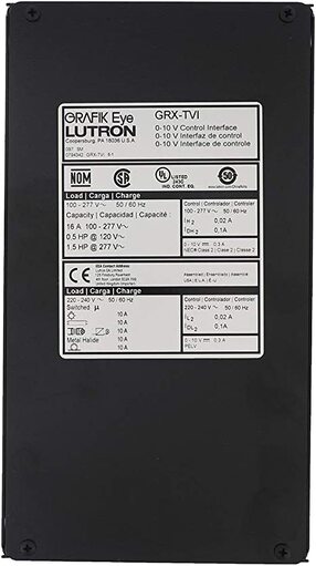
Closeup of a Lutron GRX-TVI.
The GRX-TVI is system agnostic and can be used with wall-box dimmers, up to whole building processor-based controls. The TVI accepts an analog, phase dimming input and converts that input to a 0-10V dimming signal. In addition to creating a 0-10V signal, the GRX-TVI can be used to allow a 120V dimmer to power a 277V fixture, and vice-versa.
When you open the GRX-TVI, you will see 3 sections of terminal blocks. I prefer to think of each section separately, which helps troubleshoot the unit. The left-most section is called, somewhat confusingly, section 2, containing 4 terminal blocks labeled Line 2/Line 2/Neutral 2/Dimmed Hot 2. This section is where the wiring related to the phase dimmer is landed.
The first two terminals, both labeled Line 2, are where we see most of our wiring problems. These two terminals are internally shorted, and either terminal can be used (or one can be used as a jumper point to section 1, which we will describe below). The purpose of the line 2 terminal is to land the constant hot wire, fed from the same circuit as the dimmer being used to drive the GRX-TVI.
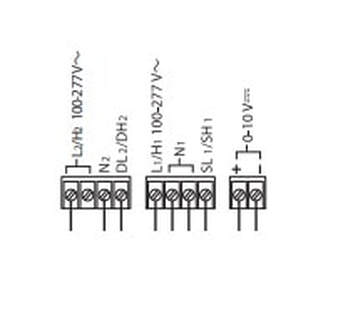
The internal wiring terminals of the GRX-TVI.
So, for example, if the TVI is being used to convert a wall-box dimmer to a 0-10V controller, L2 would need the same circuit as is feeding into the wall-box dimmer. If a Lutron GP panel is being used, the L2 terminal would be fed with a wire from the same circuit of that panel.
We will often see a different constant hot land here, which will cause issues. You can get away with using a different circuit, so long it is of the same phase as the dimmer, but a feed here of a different phase WILL NOT WORK.
N2 is the associated neutral for this circuit, and DL2/DH2 is the dimmed line/dimmed hot coming from the dimmer being used.
Section 1, or the center section, is all about the fixture. The L1 terminal is for the hot input being used to power the lighting zone in question. The two N1 neutral terminals are for the associated neutral (they are shorted internally, but one can be used for the neutral to the panel, and one can be used for the neutral to the lights). Finally, SL1/SH1 is the Switched Line / Switched Hot powering the lights. This is a relay output that will turn the zone of lights on and off by powering and un-powering the switch leg out.
Sections 1 and 2 of the TVI are physically separated, and this is because they can be different voltages and phases. If the dimmer is one voltage and/or phase, all that wiring will land on section 1, while the fixture wiring will remain on section 2. This allows a 120V dimmer on phase A to control a 277V fixture on phase B, for example.
If, on the other hand, the dimmer and fixture are of the same voltage and phase, the TVI can share the same input circuit between sections 1 and 2. In this case, a jumper wire can be installed between L1 and L2, and a separate input would not be required.
Lastly, in the far right of the TVI is the low-voltage section, where the positive and negative 0-10V wires for the GRX-TVI are landed. The TVI is a sinking device, and will only work with ballasts and drivers that source 0-10V.
Conclusion
When you run into problems with your 0-10V lighting, it helps to know how to troubleshoot it. By following this general guide, you can determine what the potential problem is and figure out the next steps to get your lights working properly.
Need help troubleshooting your 0-10V lighting? Contact us to discuss your problem so we can help your lights work again.